Satpack hardware part 2
The pcbs shown in the previous posting have mated very nicely with the Arduino Mini Pro. The first photo shows the side with the Arduino.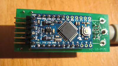

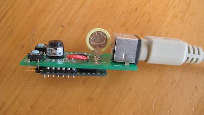
This photo from the side, and shows the hardware on the top of the pcb. From left to right these are, two pushbuttons, a piezolectric speaker for CW, a battery for the realtime clock and a mini-din 8 connector to connect to the FT-817 radio through a standard mini-din 8 cable.
 Here, finally, is the underside of the pcb without the mating Arduino Pro Mini. You can see that the realtime clock chip is thin enough to sit under the Arduino .
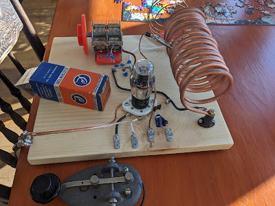

Bruce,
ReplyDeleteCould you provide a code snippet for using the RTC to set the time for the Arduino? I'm having a little trouble getting my head wrapped around I2C communications.
I got my BBB Arduino going, but the processor doesn't have enough code space to do anything with Plan13... dooh! I'm going to acquire a Mini Pro board soon so that will take care of the issue.
73,
John K2ZA
Also, I have started a blog of my own:
ReplyDeletek2za.blogspot.com
73,
John K2ZA