Building and Operating a Transmitter from the Roaring 20s

.jpg)
The 1929 QSO Party
Every year the Antique Wireless Association holds a two-weekend event dedicated to winding back the clock to this age. During this Bruce Kelly 1929 QSO Party, dozens of transmitters home-built according to pre-1930 techniques contact each other on the160m, 80m, 40m and, for the very brave, 20m bands. Some actual antiques join the fun, too. The rules are reasonable: you don't need to use parts manufactured before 1930, but they -- and the accompanying circuit -- have to be of a type that was developed in that period. This keeps the price of building a transmitter affordable. Indeed, a favoured one-tube 'Hartley' design uses the modestly priced and widely available type 27 tube.
I heard about this from Mike WU2D's excellent YouTube channel back in April or May, and I was intrigued, partly because my father, who was visiting my town for the summer, was born in 1929, and as a practiced woodworker he'd be game to help me with the breadboard design. Even better, the AWA had a simple design offered on its website.
Putting the Transmitter Together
But how would I find a power supply? That problem always seemed to complicate tube transmitter projects: sure the transmitter itself is only 10 parts, but it's at least as much work to get the 300 volts of DC at 25 watts to supply it. Only days later, Aliexpress offered an exciting solution, a DC 12V to DC 200-450V boost converter that boasts 70W! At under $10 I ordered it half expecting it to be too noisy or unstable to use. I didn't like its open design, so I designed and 3D-printed a slide-over cover for it to keep me from zapping my fingers. It was surprisingly 'stiff' under a load, had only a bit of ripple and didn't overload my receiver with hash. Sure, some day it would be great to build a tube-based power supply for these tube projects, but for me the project really got going when I knew I had the power worked out.
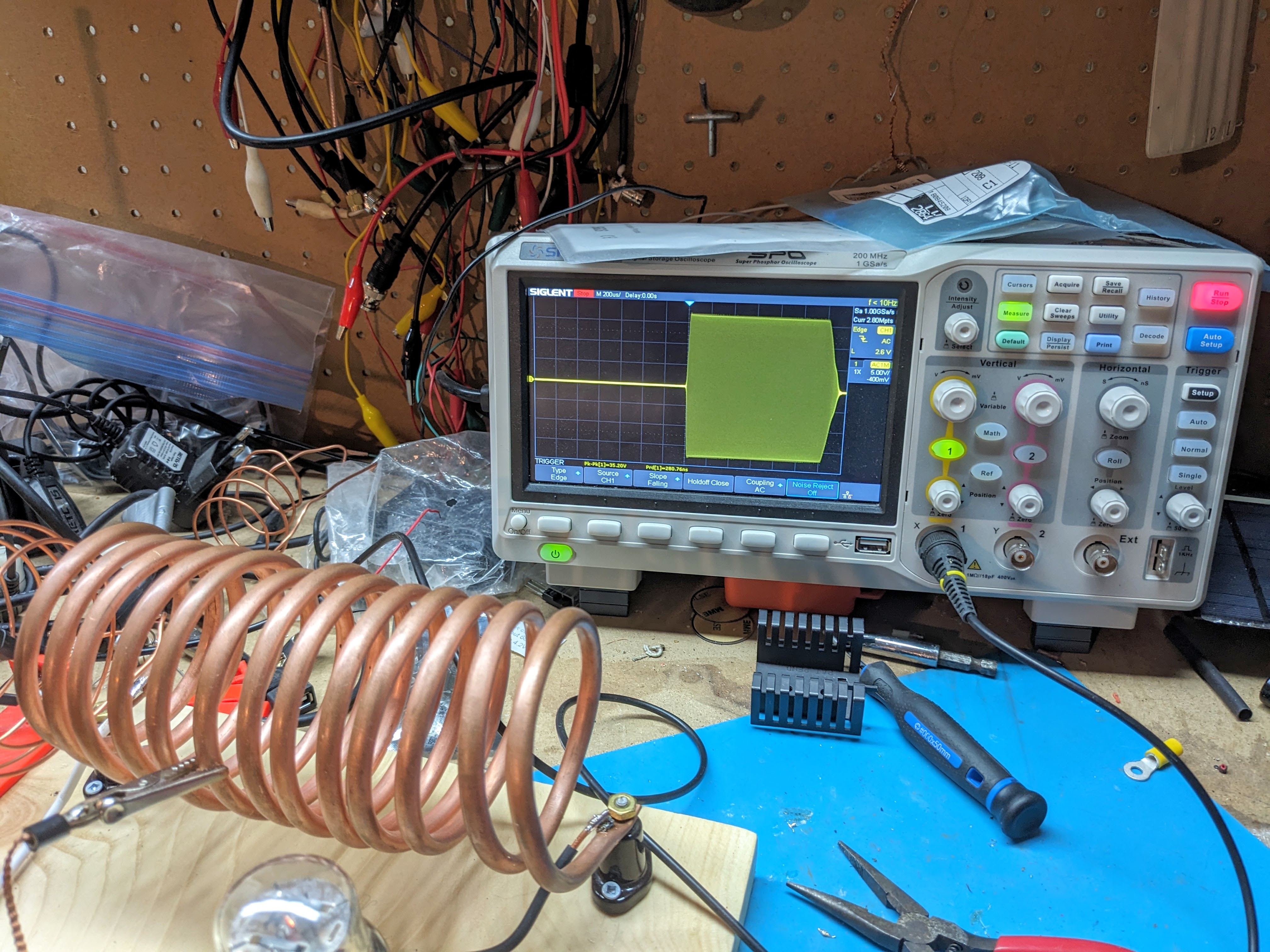
From there on, it was a matter of either finding parts in my junk box, ordering them online or buying at the hardware store. Brackets, adapter plates and a tuning dial were printed in 3D. (I meant to replace these garish orange parts with ones printed in a wood-based material, but I ran out of time.) Brass screws were used as soldering posts and ordinary housing wire used to hook everything up. I was able to find a suitable 2.5mH inductor at Digikey, and I ordered a bunch of 1000v capacitors to design the tuned circuit. I used my nanovna to verify that the 12 turns of iconic 1/4" copper tubing and the capacitor network were tuned in the 80m band.
Next, the antenna. I had a 40m end-fed halfwave antenna that needed an upgrade, so I replaced its 20m wire with 40m strung up about 30' in the air. I made a few contacts with New England using the 2 watts of energy I could expect from the homemade transmitter, and all seemed good. (An antenna for this band at this height is expected only to operate relatively local stations, say up to 1000km, but that's preferable for such a weak signal.)
A day before the first weekend of the event, I fired the transmitter up and ... nothing. No radio frequency radiation, anyway: the circuit was pulling power, but not resonating. I tried changing the grid-leak resistor and capacitor. Then I just took out of the circuit all the fixed capacitors that I'd soldered in to lower the tuning frequency, figuring they were the greatest number of components in the whole circuit. Voila! It turns out one of them wasn't up to the task. Only one problem: without those capacitors, I was making radio signals 2 MHz away from the 3.5 MHz 80m band. I gave up on transmitting during the event's first weekend, and vowed to get everything in place for weekend two.
Finishing Touches
Junk box capacitors were pressed into service to pull the transmitter down to the 80m band and then I made a coil out of house wire to pick up the generated signal and send it off to the ether. At this point the output power could be measured: 0.7 watts! Not great. The size and position of the pick up coil would vary the amount of energy coupled into it, so I experimented with that a bit and got up to 1.5 watts with 250v power supply.
That is a great build my friend.
ReplyDeleteAll the best to you, and thanks for today QSO on 15 CW
73 de Oliver, HB9IIH