Defining a 49:1 EFHW Transformer's Losses
 End-fed halfwave antennas are so convenient, especially in rapidly deployed setups, and they're easy to build. But how much energy is lost in the 49:1 transformer that makes it possible? Because I operate mainly QRP, and I'm using a rather large core for 5w, I'm not concerned with losses that appear once the transformer's core reaches the Curie temperature. So I can use a nanoVNA, performing a S21 logmag trace on two cores back-to-back, to see how much power my transformer is eating up on the way to the antenna.
I used the Fair-Rite 2643625002 core, inspired by excellent results MM0OPX reports in a generously shared spreadsheet of results. Could I get around 0.5 dB loss from 80m all the way to 10m if I used that core in 21:3 turns ratio?
My experience with more donut-shaped ones suggested that such broad-banded performance was a tough order: a 14:2 turns ratio works well on one end of the HF band; 21:3 works well on the other. In the end, Colin's accompanying video recommends the larger Fair-Rite 2643251002, but it's back-ordered at Digikey. Maybe Colin should have warned Fair-Rite that he was going to increase the market for this core!
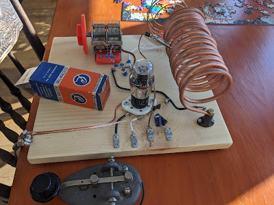
Here's a picture of one of the completed transformers, connected to an sma female jack.


So I'm getting about .5dB worse performance on 10m than MM0OPX but slightly better on 17m and below. It is worth fiddling with the spacing of your turns on the cores: I probably shaved off 1 dB per core at 10m by evening out the spacing. Note that with other core designs, I (like others) found that bunching the winds up on one side -- i.e., doing exactly the opposite -- similarly improved performance.
Let's put this approximately 1 dB of loss in perspective. It represents about a 20% reduction in power, dropping my full-gallon QRP signal to 4 watts. But that 4 watts is fed directly into the transmitting wire of the antenna. Compare this with a (perfectly matched) run of RG-58 to feed an inverted vee from its midpoint. Say it's up 25 feet (8m). Well, this will introduce 0.8 dB of loss before the the wire, about the same as this core. And if someone uses RG-174 for the same purpose, perhaps in a portable set-up, the losses will be much more, and significantly worse than this core.
I have some recommendations for measuring these losses. Obviously, any metal near these will change the character of one of the cores more than the other thus causing an imbalance and causing the system losses to be higher. Next time I do this, I should measure the values of the capacitors, making sure they match well. It occurs to me that a difference here might well also imbalance the two transformers, making the back-to-back performance worse than what a single core would see.
Comments
Post a Comment